|
Appendix
robo_cad User's
Manual
Three-dimensional computer animations of robotic systems may be created using this application program. One, two and three degree of freedom joint modules and generic links are used as the basis of this modular and reconfigurable animation package. These modules may be assembled into a large class of robotic systems that include serial, parallel, mobile and hybrid configurations. The animated model is created by specifying which modules are used and how they are connected.
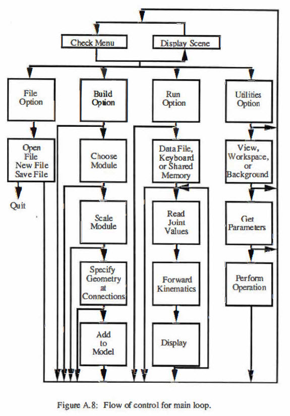
The main menu bar is at the top of the screen and contains the options "FILE", "BUILD", "RUN" and "UTILITIES". These menus are of the pulldown variety and may be activated by positioning the cursor over the desired option and clicking the right mouse button. The right mouse button is used throughout this program. All lengths are in meters and all angles are in
degrees.
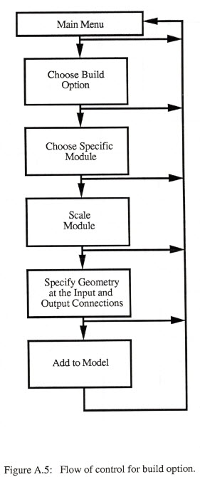
A.1 Build
The BUILD menu is used to assemble the modules into the robotic structure. The building procedure relies upon the idea of a drawing frame. The drawing frame used in this program is Cartesian. The frame is translated and rotated in space to provide a local origin for each module. The translations are performed first and then the rotations are performed in the order x, y and then z. Each module is added to the robot model relative to this frame and may change the frame before adding the next module. The program begins with the frame in the position and orientation of the universe frame: zero x, zero y and zero z position and orientation. This x axis of the universe frame points out from the screen, the y axis goes from left to right and the z axis points up. If the view is changed this will no longer be true.
In general each module uses six arguments that may move the drawing frame before a module is added and six arguments that may move the drawing frame after the module is added. The program calls these the input frames and the output frames respectively. The modules also need to be scaled. The scaling parameters are the diameter, length, height, width, etc. With some modules the input and output frame locations are determined by the scale and the type of module used. These modules will require fewer arguments, twist angle for example, for moving the drawing frame.
Clicking the right mouse button while the cursor is positioned over the word "BUILD" in the main menu will cause the BUILD menu to appear. In this menu are the choices "add joint", "add base", "add link", "end effector",
"environment" and "parallel". Releasing the mouse button when the cursor is positioned over one of these choices will cause its associated dialog box to appear. The parallel dialogue box will ask for six arguments that will specify the position and orientation of a branching chain relative to the current position of the drawing frame. The other dialogue boxes will ask for a more specific choice of which link, joint, base, end effector or object in the environment you want to build with. Click on the specific module and then click in the OK box. Clicking in the cancel box will cause the program to return to the main menu.
A.1.1 Serial
This program assumes that modules are being added to the robot in a serial fashion unless it is told otherwise. Modules are added relative to the position and orientation of the drawing frame active when the build option was selected. The first module will be added relative to the universe frame. This module may move the frame for the next module. The input frame parameters move the drawing frame before the module is added and the output frame parameters move the drawing frame after the module is added.
A.1.2 Parallel
A parallel structure may be formed by specifying the proper joint angles to close an open serial chain. The parallel option in the menu tells the program that the current serial chain is branching. The parallel dialogue box asks for six parameters that will specify the position and orientation of the branching frame relative to the current drawing frame. The next modules will be added as a serial chain that begins at the branching frame. The program will continue to add modules to the branching chain until an end effector is added to the chain. The end-
effector is a signal to the program to terminate the current chain and return to the drawing frame that was active when the parallel option was invoked. Terminating the first chain with an end effector will cause the universe frame to become active. Invoking the parallel option when the universe frame is active can be used to create multiple robots operating independently in the same environment. Attempting to create multiple chains without using the parallel option or adding more end effectors than there are chains will
have. unpredictable results.
A.1.3 Mobile
A mobile robot is created by attaching degrees of freedom to the base frame of the robot. There is a moving reference frame among the choices of bases. This frame takes six parameters and can be used to create a mobile robot that can move to any position and orientation in the environment. The moving reference frame can also be used to create objects that can move around in the environment, for example a pick and place operation or a falling object. Sliders and revolutes can be used to create a mobile robot whose base frame motion has less than six degrees of freedom. The parallel option can be used to create multiple mobile robots.
A.1.4 Hybrid
A hybrid robot has both parallel and serial parts. The hybrid robot can be assembled by branching into multiple serial chains and then specifying the
proper joint angles to close someof the chains. A hybrid robot can
also be created by adding inherently parallel modules, such a sthe spherical shoulder, to
a serial chain. The parallel modules do not require that all of the interior joint angles be specified. The shoulder, for instance, only requires roll, pitch and yaw and then will automatically calculate the proper interior joint angles.
A.1.5 Environment
The environment menuis for placing objects in the environment. Each environment module requires six arguments that position and orient the module in relation to the universe frame. Objects added from the environment menuare fixed in their position and orientation and QQ.llQ1 affect the active drawing frame. Available in the environment menuarethe simple graphics primitives box, wedge, tube and cone. These primitives may be used
to assemble more complex objects.
A.1.6 Example
This is a simple example of constructing a serial three degree of freedom robotarmmountedon afixed pedestal. Begin by running the modular cad program. A window should open with the words "FILE", "BUILD", "RUN" and "UTILITIES".
 |
|
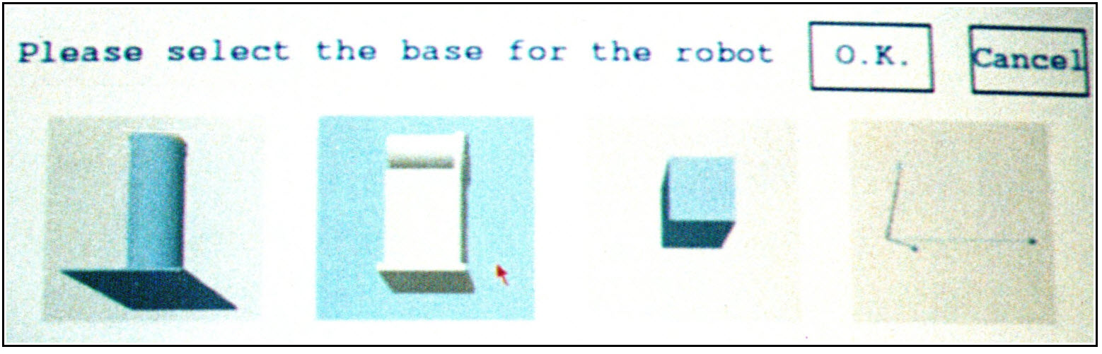
Figure A.1: Select a base for the robot. |
Select from the build menu by clicking the right mouse button when the
cursor is over the word "BUILD". Look at what bases are available by releasing the button when the cursor is over "add base." Select from among the bases by positioning the cursor over the desired base and clicking the right mouse button. Select the revolute mounting pedestal and then click on the box labeled OK. A dialogue box will appear with
a three-dimensional display of the revolute mounting pedestal. Choose either the slanted or the horizontal stand and the color of the pedestal by clicking
on the appropriate button. The button should push in to verify the choice. Click on the OK box to add the base to the
robot model.
 |
|
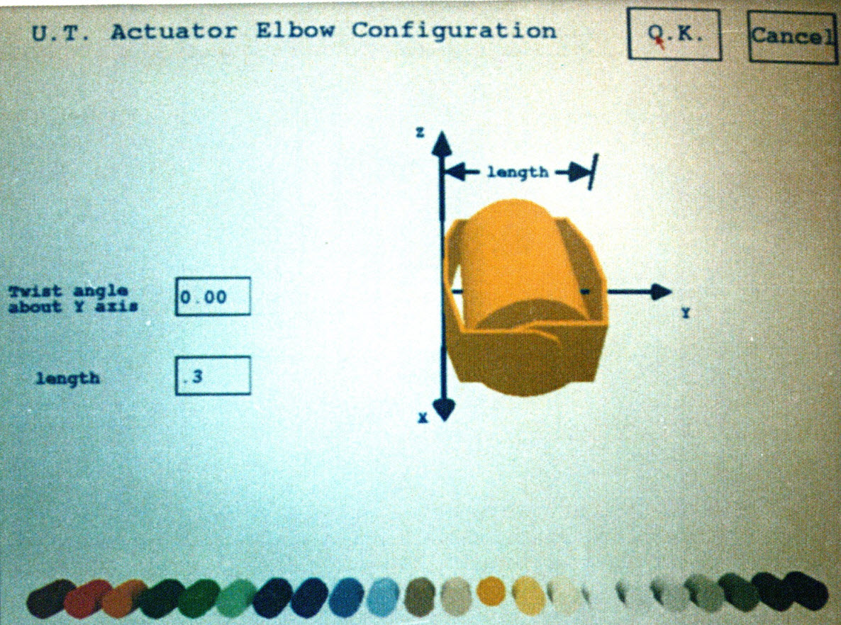
Figure A.2: Scale and select the color of
the joint module. |
Select the U. T. actuator from the "add joint" option in the "BUILD" menu. Scale the module by specifying the length as shown on the display. Specify the length by clicking on the box next to the word "length" in the dialogue box. Then type in the length using the keyboard. About .35 meters is fine. Choose the color, then click on the OK box. This module is now added to the robot model.
 |
|
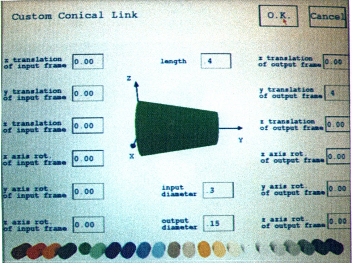
Figure A.3: Scale, color and specify the
connection geometry of the link. |
Now select the U. T. actuator in-line configuration from among the joints in the "add joint" option under the "BUILD" menu. Specify the two lengths shown in the dialogue box, choose the color and then click on OK. This module is now added to the robot model. Select the conical link from among the links in the "add link" option under the "BUILD" menu. Specify the length, input diameter, output diameter and color of the link. Specify the y translation of the output frame to be the same as the length so that the next module will be added onto the end of the
link.
Add a parallel jaw end- effector to the robot model by selecting from among the end effectors in the "end effector" option under the build menu. Animate the model by selecting "keyboard" from the "RUN" menu. Keys 1, 2, and 3 will increment and keys Q, Wand E will decrement the three joints
respectively.
 |
|
Figure A.4: Animate the finished model. |
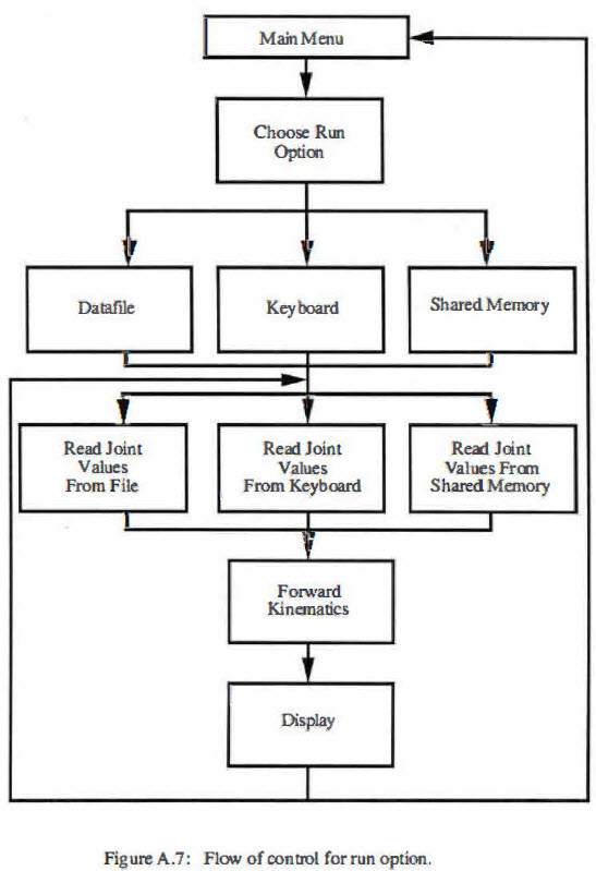
A.2 ANIMATION
The animation effect is created by showing rapidly in succession the robot scene with the joint angles changed by a small amount in each scene. This gives the illusion that the robot is moving. The models created with this program can be animated by accepting data from the keyboard, from data files or in real-time via shared memory.
A.2.1 Animation from Keyboard
The simplest way to animate the robot is to use the keyboard to increment or decrement each joint directly. The joints are numbered in the order that they were added to the model. The specific keys and the joints that they affect are shown in a small box that will appear near the top of the screen. Animating from the keyboard is useful for demonstrations and testing. Select "end run" from the run menu to stop animating from the keyboard.
A.2.2 Animation from Datafiles
Running the animation from a data file is an excellent method of viewing the results from inverse kinematics algorithms or dynamic simulations. To run from a datafile simply choose "datafile" in the run menu. A dialogue box will ask for the name of the datafile that is to be animated. Type in the name of the datafile and choose whether to step or cycle through the data. If step is chosen, the computer will show the next position each time the right mouse button is clicked. The first two lines in the datafile are reserved for comments which must be terminated by a carriage return. The next line must contain the number of degrees of freedom in the system as an integer. All of the following lines must contain a floating point number for each degree of freedom and all lines must be terminated with a return. The rotational degrees of freedom are specified in degrees and the translational degrees of freedom are specified in meters. An end-of-file token must mark the end of the file. Failing to follow this format for the data file exactly will produce unpredictable results.
A.2.3 Animation from Shared Memory
Running the program from shared memory allows the real-time animation of data as it occurs. Selecting "shared memory" from the RUN menu will cause the program to create a shared memory segment. The program will continuously read from this shared memory and display the robot in the position defined by the joint angles until "end run" is chosen in the RUN menu.
The shared memory segment is simply a one-dimensional array of floating point numbers. The program considers the first number in the array to represent the value of joint variable one, the second number joint variable two, etc. To animate the robot in real-time simply run in another window a process that is repeatedly generating joint angles and write the data into the shared memory segment. Sample code for doing this may be found by selecting "shared memory" from the "RUN" menu and then clicking on the area marked "sample code" in the shared memory dialogue box.
A.3 FILING SYSTEMS
After a robot animation has been constructed, it may be saved and later recalled. The robot, objects in the environment and the viewing parameters will be saved. The joint angles are not saved and all joint angles will be set to zero when a robot model is recalled from a file.
A.3.1 Save Robot File
To save a robot model after it has been constructed simply select "save" from the "FILE" menu. Click in the name box and then type in the file name. Click OK to save the file. The program will write over any file of the same name in the current directory.
A.3.2 Open Robot File
To open a robot file simply select "open" from the "FILE" menu. Click in the name box and then type in the name of the file that is to be displayed and then click on OK. There will be an error message if the program cannot open the specified file. Opening a file will erase the current display.
A.3.3 New File
Selecting the "new" option from the "FILE" menu will display a small dialogue box. Clicking OK in this dialogue box will erase whatever is currently being displayed, return the active drawing frame to the universe position and reset the viewing parameters.
A.3.4 Quit
To end the program select "quit" from the FILE menu. The main menu bar, which is drawn into overlay planes, will not be erased if the program is not exited in this manner.
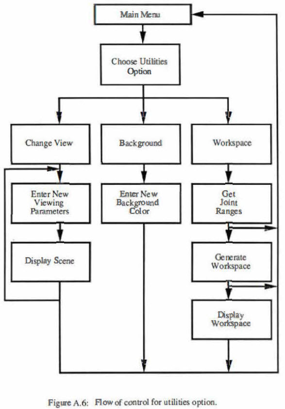
A.4 UTILITIES
The "UTILITIES" menu contains view, workspace and background options. The view option is used to specify the viewing parameters for the animation. The workspace option can be used to generate a graphical description of the reachable workspace of the robot. The background option sets the background color of the display.
A.4.1 View
Selecting the "view" option will cause a dialogue box to appear that can be used to adjust the viewing aspect for the scene. Note that the commands are given relative to the viewer. "Move up" means to move the viewer's eyes up, hence the scene will appear to move down. There is also an option to display the scene with orthographic or perspective viewing projections. The perspective projection allows objects to be zoomed into for a higher precision display. Orthographic projections provide higher performance.
A.4.2 Workspace
The reachable workspace is generated by cycling the robot animation through a series of positions and leaving a token at the end effector for each position. The token is a triangle whose normal points along the y axis of the last module in the chain. The workspace dialogue box will ask for a range of motion and a step size for each degree of freedom. The color buttons specify the color of the triangular token. The workspace generation is quite computationally intensive and will take a long time if large ranges are used with small step sizes. The program will indicate the approximate amount of time in minutes that the calculation should be expected to take..
 |
 |
 |
 |
|