|
Chapter 4
Specific
Developments in this Report
The incorporation of modularity and reconfigurablility into the computer animation of robotic systems facilitates the application of computer animation to many areas of robotics research. Animations of an extremely large class of robotics systems can be created by simply assembling together modules from a finite set of one, two and three degree of freedom joint modules and generic links. The hierarchical nature of robotic systems makes the interpretation of kinematic data in numerical form very difficult. Computer animation is an effective method of visually presenting kinematic data, such as might be generated by obstacle avoidance algorithms, redundant inverse kinematics routines and as the output from dynamic simulations. If the computer is continuously animating data as it occurs in response to external events, the animation may be said to be running in real-time. The ability to run in real-time allows the animation to be used in the development of manual controllers. Modular and reconfigurable animation can be used in the development of serial, parallel, mobile and hybrid manipulators and is ideally suited to the development of modular and reconfigurable robotic systems. The ability of the computer to mathematically scale the display to a very fine resolution allows the animation to display precision operation. A modular approach to animation may be used to generate world model databases that include multiple robots and obstacles that may be fixed to the universe frame or may move about in the environment to simulate task performance.
4.1 Obstacle Avoidance
Obstacle avoidance refers to moving the robot about in the environment while avoiding collisions with objects in the environment. The obstacles may include the robot itself, fixed objects in the environment, moving objects in the environment and also other robots that may be operating in the same workspace [ 43]. The cost of an industrial robot colliding with an obstacle in the environment could be very high, both in terms of repair to the robot and the environment as well as the cost of lost productivity due to downtime. The results of a collision in a more sensitive environment, such as space, nuclear or military applications could be enormous. The cost of such collisions makes obstacle avoidance of fundamental importance when planning the robot's path.
The schemes for performing obstacle avoidance might loosely be divided into two groups, those that address obstacle avoidance from a local point of view and those that address obstacle avoidance from a global point of view. Global methods evaluate the robot and the environment and attempt to find a continuous collision-free path from a starting position to a goal position.
 |
|
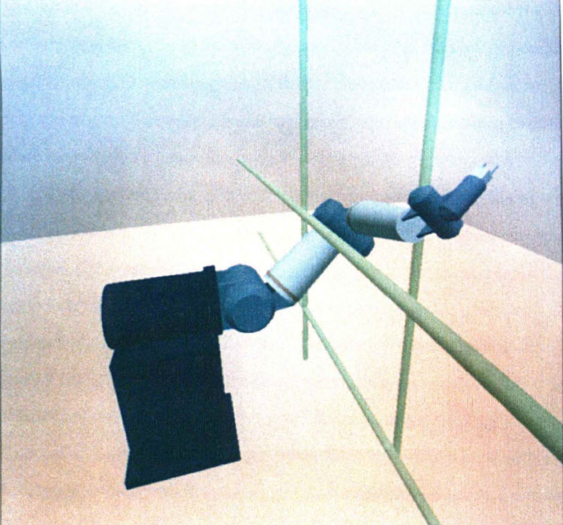
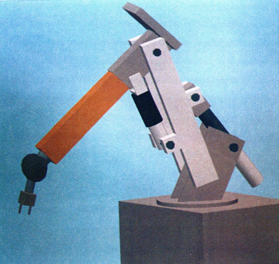
Figure 4.1: Robot performing an obstacle avoidance
maneuver. |
A common approach to global obstacle avoidance is to arrange the obstacles as vertices in a graph [14]. Collision-free paths to the goal are found as a sequence of edges along the graph. Local approaches examine the robot and the environment at each step as the robot follows a path from the starting position to the goal position. Imaginary potential fields may be created around the robot and the obstacles. The positions and overlaps of these fields are then evaluated at each step along the path.
Computer animation of modular and reconfigurable robotic systems can be used as a tool in the research of both global and local obstacle avoidance techniques. The same database that is used to generate the modular robot and the modular environment can also be used as a database for the obstacle avoidance algorithms. The animation can also show the boundaries of any potential fields that are used by the obstacle avoidance routines. Moving obstacles can be created by attaching to the obstacles degrees of freedom referenced to the universe frame. A robot performing a task, such as pick and place, might be simulated in this manner. A valve might be simulated as a two degree of freedom screw joint attached to the environment. The robot opening or closing this valve could be simulated by specifying the proper joint displacements.
4.2 Redundant Robots
A redundant robot has more degrees of freedom than are necessary to specify the state of the end effector. Any robot with seven or more degrees of freedom is redundant because it only takes six parameters to specify the position and orientation of an object in three-dimensional space. The extra degrees of freedom can be used to improve the performance of the system by allowing the end effector to reach the goal with many different joint paths. Different criteria can be used to determine which joint paths are best for a given situation [5]. The inverse kinematics are complicated by the fact that the Jacobian of a redundant robot cannot in general be uniquely inverted. Other methods must be used to determine what to do with the extra degrees of freedom. Wal.king machines, multifingered grippers and "snake" manipulators are all examples of redundant robotic systems.
Many different methods of incorporating the extra degrees of freedom into the inverse kinematics algorithms for redundant robots have been developed. Since there are many different joint positions that will result in the same end effector position, redundant inverse kinematics is often approached as an optimization problem where many different criteria are considered. Local methods solve the inverse kinematics at each discreet point along the path, while global methods consider the path as a whole. A pseudoinverse of the Jacobian matrix is often used to solve for the inverse kinematics of the redundant robot [30]. The pseudoinverse does not in general give a unique solution. Thus, cyclically following the same end effector path does not guarantee repeating the same joint paths. Multiple criteria have also been incorporated to resolve the kinematic redundancy. These criteria include singularity avoidance, obstacle avoidance, robot dexterity, energy minimization, manipulator precision, load carrying capacity, speed of operation and others [5]. Complicating the incorporation of multiple criteria is the fact that the multiple criteria can be in multiple energy domains, have different units and be of very different magnitudes. This requires that the criteria be properly normalized and prioritized [5]. Another method of solving redundant inverse kinematics breaks the redundant chains into smaller chains that are not redundant and may be solved by direct inversion of the Jacobian (18]. The solution is constrained such that the cut ends have the same spatial position, velocity, and acceleration. The position and trajectory of the cut point may be chosen such that the resulting inverse kinematics solutions are well behaved, or by other decision making or intelligence schemes. Genetic algorithms have been used to find inverse kinematics solutions for redundant robots [34]. Genetic algorithms are search procedures that are based on genetics and natural selection. A simple genetic algorithm generates solutions and then chooses which algorithms will propagate based on their fitness, where fitness is the maximization of some performance
criteria.
|
|
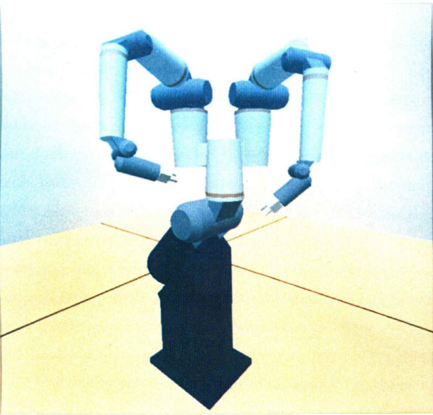
| Figure 4.2: Seventeen degree of freedom redundant robot |
By definition, redundant robots have extra degrees of freedom. More computer programming time is necessary to generate the forward kinematics and visual simulation for these extra degrees of freedom. This time is significantly reduced by using computer animation based on a generalized modular and reconfigurable mechanical architecture. A robot with extra degrees of freedom simply has more joint modules and generic links. The extra degrees of freedom makes the interpretation of kinematic data in numerical form even more difficult, thus adding to the benefit of displaying this data graphically.
The many criteria that may be used by the inverse kinematics schemes may also be presented graphically by means of computer animation.
4.3 Dynamic Simulation
Dynamic modelling of robotic systems is an active area of robotics research [4] [6] [21]. Dynamic modelling incorporates mass, compliance and damping to simulate the system response to joint forces and external loads. Computer animation can be used to display the results from these dynamic simulations.
Dynamic models can be used to evaluate the dynamic condition and performance of a robot as it performs a task. The condition number of the Jacobian matrix has been suggested as a performance measure [38]. Singular values of the Jacobian may also be incorporated into an evaluation procedure [53]. The state of the inertia matrix has been used as a measure of the robot's dynamic ability [23]. The dynamic model can be incorporated into feed forward control algorithms. Feedforward control incorporates the system dynamics into the control algorithm in order to synthesize the output. The dynamic model for the robotic system may be developed in terms of kinematic influence coefficients [ 48]. The kinematic influence coefficients employ the geometry of the robot to relate the system's dynamic characteristics as they appear at any input to the system.
Computer animation is by nature kinematic. An animated robot can exhibit high speed, high precision, no deformation and no backlash. This is, of course, a tremendous simplification. By coupling a dynamic model to the animation it is possible to make the robot appear to move in a more realistic manner. A modular and reconfigurable robotic architecture presents an excellent opportunity to combine dynamic simulation and computer animation. Constructing the graphical robot on the screen defines the modules that make up the robot and the geometry . The dynamic description can be stored as a feature within the modules. As each module is added to the robot, the dynamic equations could be automatically generated using the geometry and the dynamic description of the modules. The incorporation of dynamic analysis with realtime control can be studied with computer animation by running the animation continuously on the data as it is being generated by the control algorithms. The animation also provides a method of graphically displaying performance measures as the robot performs a task.
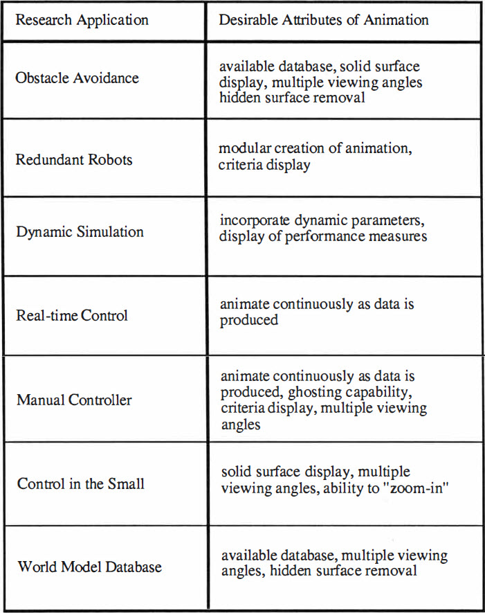 |
| Table 4.1 Desirable attributes
of an animation package for various research opportunities |
4.4 Real-Time Control
The real-time control of robots has been the subject of many recent robotics research papers. A good definition for real-time control in robotics seems to be "while the robot is moving". In other words, the real-time controller continuously sends commands to the robot and operates on sensory information as the robot performs its task. By this definition the difference between recent real-time control schemes and previous controllers is that the more recent real-time controllers are based on digital computers and
microprocessors.
Recent work in real-time control has included the development of realtime computer architectures and real-time programming languages [27] [36] [ 40]. These real-time control schemes dynamically allocate the computers resources in response to external events. The events may be generated by external sensors that provide information about the environment and the state of the system, or the events may be generated internally perhaps in response to some calculation reaching completion. The response of the controller to events is typically priority-based [27]. An important consideration with real-time controllers is the context switch time. The context switch time is the amount of time it takes the computer to stop what it is doing, save necessary data and begin responding to another event.
A computer animation that is continuously animating data as it is produced is running in real-time. The data may be produced by another process that is residing on the same computer, or the data may be produced externally by another computer or a manual controller. The data might also be generated by the robot itself with strain gauges, resolvers, etc. The animation can also take desired data from the controller and actual data from the robot and display the difference between the two. By running the animation in real-time the computer can become an animated robot testbed.
4.5 Manual Controller Development
The manual controller is the interface between the man and the machine. This interface should support two-way communication. That is, the human should be able to send commands to the robot and the robot should be able to relay sensory information back to the operator. The interface is complicated by the need to transform between the robot geometry and the controller geometry. There exists the possibility of replacing the manually controlled robot with a fully autonomous robot. There are, however, many benefits to be obtained by keeping the human in the loop. These benefits include the ability of the human to provide redundant control in cases of autonomous control system failure, unexpected changes in the operating environment and tasks too stringent to be addressed by the current state of the art in autonomous control [41].
Modern manual controllers attempt to provide a feeling of telepresence. In addition to visual information there is a tremendous amount of proprioceptive feedback when a human physically performs a task. This feedback includes net forces and the distribution of forces. An articulated manual controller with actuated joints can be used to provide force feedback.
Modern robots incorporate multiple sensors that provide information about the system state and environmental conditions as the robot is performing its task. The computer animation can be used to provide a dynamic graphical display of this information. The animation can be used to provide common visual information, such as the positions and motions of the robot and objects in the environment . The animation can also provide information about many other system criteria, such as force distribution, stress distribution and energy consumption. The animation can display multiple viewing angles and can warn of impending collisions or close approaches between surfaces. By incorporating a dynamic model the animation can predict how the robot will respond given input commands from the manual controller. These input commands can be modified until acceptable results are obtained and then be given to the actual robot. The modular and reconfigurable architecture can be used to rapidly build many different robot configurations. These animations can then be used to evaluate the performance of universal controllers that are not dependent upon the robot geometry.
The computer can also be used to display animated ghosting of the robot manipulator. Ghosting refers to displaying two images of the manipulator in the same scene. One image could be used to display the actual position of the manipulator while the other image, the ghost, could be used to display the desired position.
4.6 Serial Robots
A serial robot is created by connecting a number of one degree of freedom joints in a series. The output of each joint is connected to the input of the next joint by a link. This sequence continues until the end effector is reached. The end effector terminates the serial robot and is used to interact with the environment in the performance of the robot's task. The serial structure results in a hierarchy where the movement of one joint changes the position and/or orientation of all distal joints and links. The serial structure also propagates errors throughout the system. Errors that occur at an interior location may be amplified by the robot's geometry and show increased effect at the end effector. The serial manipulator must also support the load of its own actuators, or suffer decreased precision due to the compliance inherent in torque transmission devices, such as torque tubes and tendon drives. The serial manipulator tends to have a large workspace and good dexterity.
A representative dynamic model must be used to precisely control the serial manipulator. The model may be calculated using kinematic influence coefficients which are based upon the geometry of the system [ 48]. The dynamic equations can be formulated in a manner such that they may be solved in real-time (50]. Many current control schemes utilize feedback in an attempt to cancel errors at the output. The incorporation of a dynamic model allows feedforward control which utilizes system dynamics to synthesize the input
function from the desired output function. Feedback can then be used to cancel errors due to an imperfect model.
A robot animation package based on a modular and reconfigurable robotic architecture allows animations of an extremely large class of serial manipulators to be quickly assembled. These animations are created by simply connecting joint and link modules one after another. The number of degrees of freedom that the model may have is ultimately limited by the memory capacity of the computer, but thousands of degrees of freedom are possible with a modular architecture and current computers. "Snake" robots can be created by connecting together many joint modules with very short links. The modular computer animation naturally incorporates the hierarchy which determines the forward kinematics of the serial robot. Many different possible robot configurations can be graphically constructed and the animation evaluated before beginning the construction or assembly of the actual robot.
4.7 Parallel Robots
The joint angles of a parallel robot may not all be specified independently. A four bar planar mechanism, for example, has four joints but only one degree of freedom. By specifying the angle of one joint the angles of the other joints are constrained. The parallel robot typically has a smaller workspace than the serial robot, but there are also many benefits associated with using a parallel structure. The parallel structure can utilize mechanical advantage to increase its load carrying capacity. The parallel robot allows a choice among the joints as to which ones will be used as the inputs to the system. Several degrees of freedom can be obtained while still allowing direct actuation with the actuators fixed to the robot base [6]. Redundant actuation is also possible with parallel structures. The redundant actuators can provide fault tolerance and antagonistic actuation. Antagonistic actuation shows promise for high-precision tasks that require disturbance rejection.
Kinematic influence coefficients can be used as a general method of the kinematic and dynamic analysis of parallel structures [ 4]. Kinematic influence coefficients allow the dynamic and kinematic description of the system to be referenced to any joint within the parallel chain that might be used as an input to the system. This is of particular benefit for applications that involve redundant actuation for fault tolerance or antagonistic control. Computer programs have been developed that automatically generate kinematic solutions and dynamic simulations of parallel structures [21].
Computer animation of modular and reconfigurable robotic systems can be used to animate parallel structures. The parallel structure is simply built from open chains. The chain is closed to form a parallel structure by properly specifying each joint angle. This method for creating the animation is of particular benefit for the animation of data that has been generated by kinematic and dynamic analysis that treat the parallel chain as a set of constrained serial chains [4]. The parallel chain is kinematically cut, and the resulting serial chains are constrained to have zero relative position, velocity and acceleration at the cut. Errors in the kinematic solution are illuminated during the animation because the chain will appear to break at the cut.
 |
| Figure 4.3: A parallel three DOF planar manipulator with six revolute joints |
4.8 Mobile Robots
The mobile robot is able to change its base location within the environment. The mobile robot cannot, however, be expected to change its position or orientation in an arbitrary manner. The base frame of a wheeled robot, for instance, may be constrained to move in a plane. The motion of the mobile robot may also be restricted by objects in the environment. In order to plan the path of the mobile robot it is necessary to characterize the environment and the motion constraints of the robot.
The mobile robot must somehow characterize the environment in which it is to operate. One method would be to preprogram a description of the environment and store it in the robot's memory. If the environment is not completely known or is changing, then the robot must use sensors to obtain information about the environment. The sensors may include cameras, sonar, lasers and radar. The sensor data may then be used to create a map of the environment. It is also possible to use a preprogrammed database to define the objects as being in the environment and also to use sensors to identify and locate the objects . Information about the environment can be stored in a tree representation referenced to a known location. The obstacles and objects in the environment can then be referenced to the known location [8]. Various schemes have been developed to search the tree for a collision free path.
Computer animation based on a modular and reconfigurable mechanical architecture may be readily applied to the animation of mobile robots. The mobile robot is created by simply attaching the appropriate degrees of freedom to the robot base and referencing them to the universe frame. Specifying the value of the joint variables then locates the robot's base frame within the environment. Objects and obstacles in the environment can be created with the joint and link modules. A changing environment can be created by attaching degrees of freedom to the modules and referencing them to appropriate points in the environment. The viewing parameters of the animation can be varied to follow the animated mobile robot as it moves about in the environment.
4.9 Hybrid Robots
A hybrid robotic system contains both parallel and serial structures in an attempt to gain the benefits associated with each. The parallel components contribute strength and rigidity while the serial components add dexterity and reach. In excess of thirty percent of the robots in use today incorporate at least one parallel structure [12]. The Cincinnati Milacron t3776, for example, incorporates an inverted slider crank at the shoulder and wrist.
The algorithms to control the hybrid robot must be sufficiently general to handle both the serial and parallel structures. The parallel components add complication because the joint variables may not be controlled independently. The use of kinematic influence coefficients allows the kinematic and dynamic description of the system to be referenced to whichever joints are specified as the inputs.
 |
| Figure 4.4: A hybrid robot that contains two in-parallel chains |
Hybrid systems can be graphically created and animated using the generalized modular mechanical architecture. The modular animation is created by simply specifying which modules are used and how they are connected together. More than one chain can be connected to a link to create a branching effect. The extra chain can then be closed to create an in-parallel structure or left open to animate multi-arm sytems. Certain modules within the architecture, such as the three degree of freedom spherical shoulder, are inherently parallel. Hybrid systems will also be created by simply incorporating these modules within a serial chain. The equations which define the interior joint angles are stored as a feature of the parallel modules. This way only the value of each degree of freedom must be specified and the interior joint angles can be calculated automatically.
4.10 Control in the Small
Control in the small refers to small high-resolution position and force control superimposed upon the larger motions of the robot about its workspace. Control in the small can be used to compensate for errors in the robot's motion due to friction, backlash, compliance and inertia. A serious consideration in the use of control in the small to provide precise compensation for errors is the need to precisely characterize the errors themselves.
The addition of a micromanipulator between the terminal link and the end effector of the robot has been proposed as a means of providing control in the small [2]. The resulting system possesses both the large scale motion capabilities of the standard robot and the precise control characteristics of the micromanipulator. Control schemes have been developed for this type of robotic system [20]. These control schemes are reliant upon precise endpoint sensing. This may be a reasonable proposition for operation in a plane, however, precise spatial position and orientation tracking of a robot's endpoint is currently a very expensive and difficult task.
Computer animation is well suited to the visual simulation of the motions of robots possessing control in the small capabilities. Simple scaling operations can be used to mathematically magnify the display to a very fine resolution. Multiple views of the scene may also be animated simultaneously. One view could be of the entire robot from a fixed point in the environment while another view could follow the end effector motion with a very fine resolution. Both the macroscopic and microscopic characteristics of the robot with control in the small could then be displayed simultaneously.
4.11 World Model Databases
A world model database is information about the environment that is stored in the robot's memory. The robot can access this information while interacting with its environment and also use it for path planning with obstacle avoidance. The model must be complete enough to allow the robot to successfully perform its task, yet unnecessary detail will slow the interpretation of the model.
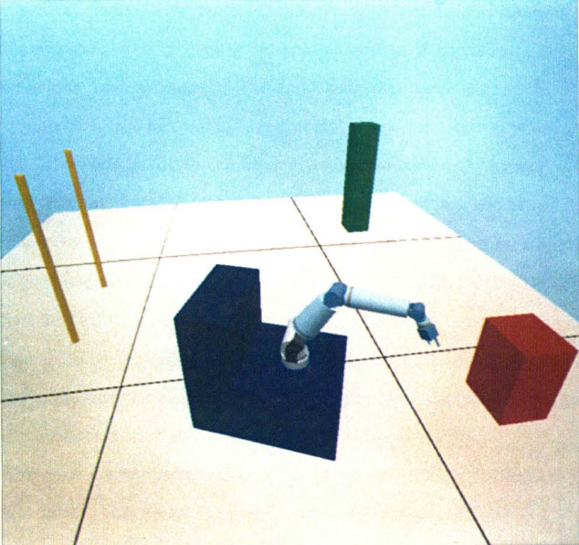 |
| Figure 4.5: A mobile robot in a simple world model |
The world model may be described in many different ways. One possible approach involves dividing the world into a three dimensional grid. Unfortunately a ten meter cubical workspace described in this way with a resolution of one millimeter has 1012 elements. This is quite a large data base to be repeatedly faced. Other methods of describing the world model are more object oriented. A list or graph of the type and location of objects in the environment can be created [8]. The world model may be entirely preprogrammed and assumed to be unchanging during the operation of the robot. The world model may also be created from sensor data by a robot performing terrain mapping operations. The two methods may also be combined by using sensor data to locate known objects within the environment.
Modular computer animation may be applied to either grid based or object oriented types of world model description. The grid-based approach may be simulated by creating a module that is the size of one element in the grid. The model is then visually displayed by putting a copy of the module in all grid locations that are described as being filled. The object-based environment may be displayed by creating modules that match the objects in the environment. The objects then may be positioned and oriented in the environment to create static obstacles, or moving objects may be simulated by attaching appropriate degrees of freedom to the obstacles and referencing them to points in the environment.
|