
|
|
Robotics Research
|
|
|
|
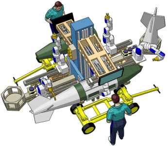
I'm currently researching the
application of AI and deep learning to collaborative robots. The
figure at the right shows a cobot work cell I was working on in
2008. Cobots are like robots, except they include safe motion
functionality that allows them to work concurrently in the same
space as people. In 2008, and in my previous research, the task
planning had to be done either by explicitly programming the
cobot with something like a teach pendant or by teleoperating
the robot with a manual controller. The goal of the current
research is to have the cobot plan and then perform its task
with only very high-level direction. This work is bringing
together object recognition and object detection from recent
advances in deep learning, classic multi-criteria optimization
techniques and current state of the art in 3D cameras.
|
|
|
|
|
The title of my
PhD dissertation was "Multicriteria Inverse Kinematics for General Serial Robots."
The inverse kinematics problem solves for the required angles
at the robot's joints to place the robot's end-effector at a
known location. People solve this problem all the time without even thinking about it. When you are eating your cereal in the morning you just reach out and grab your spoon. You don't think, "my shoulder needs to do this, my elbow needs to do that, etc."
In general, six coordinates are required to locate a rigid
body in space (for example x, y, z, roll, yaw, pitch) That's
why most industrial robots have six joints, also called
Degrees Of Freedom (DOF). Robot's with more than six joints
are known as kinematically redundant robots. The robot at left
has 8 DOF that allow it to reach through access ports and
avoid obstacles while still locating a toolpoint in six
dimensions. |
|
|
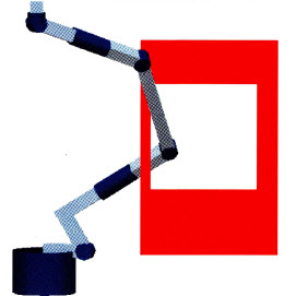
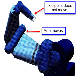
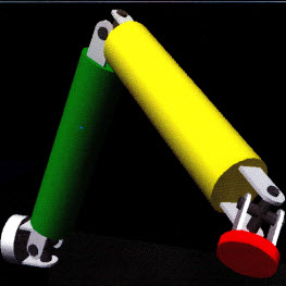
Redundant robots are capable of
self-motion, as seen at the right. This arm has 7 DOF arranged
in a geometry much like the human arm. It can locate & fix
it's toolpoint and then move the elbow to optimize some
performance metric. Think about how you might use a screwdriver
to put a screw in the wall. You put the tip of the screwdriver
in the screw and then raise your elbow so you can push the screw
into the wall while you turn it. People solve this constrained
optimization problem all the time without thinking about it. So
do monkeys. Programming computers to solve it is another matter.
Ferdinand Freudenstein, the "Father of Modern Kinematics" called
the general solution to the 6-DOF inverse kinematics problem the
"Mt. Everest" of kinematics problems. The makes the
"constrained" part of the optimization problem a
challenge.
|
|
|
|
|
Freudenstein,
however, could not have envisioned the computing power that
was coming in a few decades and in the late 1980's and early
1990's people working in the field developed generalized
inverse kinematics solutions using numerical methods and
linear algebra that could be solved on available computers in
real-time. As robot systems were being developed that had
more-and-more kinematic redundancies (I worked with two
different systems that had 17 DOF while developing the
algorithms in my dissertation), the solution to this problem
began focusing on optimization and machine intelligence.
My dissertation work compared
different optimization techniques including simulated
annealing, neural nets, genetic algorithms and direct-search, to this
constrained optimization problem. Ultimately I found the best
approaches combined closed-form solutions developed by
Freudenstein (and others) to satisfy the kinematic constraints
and the "AI" techniques for optimization. Depending
on the task, there may be 10 or 20 performance criteria that
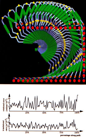
are important as robot goes about its task. The robot on the
left has 9 DOF. As it moves along its path, the values of the
different performance criteria change. The inverse solution
shown in the figure minimized the magnitude of the six degree
error vector at the toolpoint. |
|
|
Even minimizing a six degree error
vector requires combining performance criteria with different
units (rotation & translation). A number of the students I
was working with at the time were developing different
performance criteria and techniques for normalizing and fusing
them into an expression I could use in my inverse kinematics
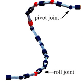
algorithms. This figure shows a 20 DOF robot NASA was
considering for inspection tasks in space. Because there would
be no gravity in space, the weight of the arm itself was not an
issue. It may be counter-intuitive, but the inverse solution for
an arm with this many joints gets easier. There are so many
solutions to choose from that this example optimized 29
different performance criteria while simultaneously solving the
inverse. The "snake" design let's the arm get into
tight places. It also supported fault-tolerance. The joints
shown in red were randomly "locked" in place while the
robot was moving. The inverse solution had to automatically
adapt.
|
|
|
|
|
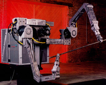
This is one of
the two 17 DOF, dual
arm robots I worked with during my research years. It was
called the Dual Armed Work Module, and it was developed for decontamination and
dismantlement of nuclear facilities. Robots are a natural
choice for working around radioactive materials. In concert
with Oak Ridge National Lab, I developed different kinematic
control modes for the robot, but the control was always "teleoperation"
in the sense the position and orientation of the robots'
grippers had to be completely remote controlled as the robot
performed its task. The robots never went about their tasks
for autonomously. This is a very tedious way of working. Just
taking the bolts off a pipe flange would take all day. It is
only makes sense for the "hottest" (radiation wise)
tasks. |
|
|
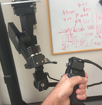
This is my hand on a Kraft
Telerobotics manual controller with force-feedback. A
force-feedback manual controller is itself a small robot. It has
motors, gears, feedback sensors, etc. This Kraft was a
nicely-executed example of a manual controller on the scale of
the human arm, though generally I preferred manual controllers
that were smaller, on the scale of a writing instrument like a
pen. I feel the muscles of the hand are more precise and have
more endurance than the muscles of the arm. A smaller &
lighter manual controller also has naturally higher fidelity in
terms of being able to feed back tactile senses to the operator.
|
|
|
|
|
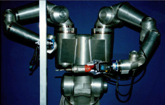
One thing I
learned during this research is that teleoperating robots to
work remotely is very hard. We had the best robots and the
best manual controllers and even simple tasks like the
drilling operation shown in this figure took a lot of practice
to be able to complete at all, let alone get clean, straight
holes. The robot needs to get its tasks at a much higher
level. That is the subject of my current research. I
wrote a paper in 1997 on kinematic control modes that had some
options on addressing these issues. Developments in AI in the
20 years since that paper should present more options. |
|
|
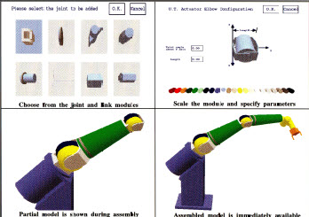
I wrote robo_cad in the late 1980's. robot_cad was a system to interactively assemble and
reconfigure modular robotic systems in a computer animation environment.
A person could assemble these modules into a large class of robotic systems that included serial, parallel, mobile and hybrid configurations. A model of the configured robotic system was immediately available for use in a wide variety of robotics research areas, including: obstacle avoidance, redundant inverse kinematics, dynamic simulations, mobile platforms and world model databases. Most of the computer graphics on this page were created using robo_cad. At the time,
NASA-JSC, NASA-JPL, Argonne National Lab, and the Universities of Texas, Maryland, Dortmund and Witwaterstrand
were using this software in one way or another.
|
|
|
|
|
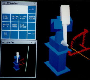
This figure
shows an offline programming interface I developed as part of
a NASA and Texas-based Universities (Rice, UT Austin, Texas
A&M, UT El Paso, and UT Arlington) research project. The
idea was to simulate a person on the ground controlling a
robot in space to perform tasks, such as inspection of space
station exterior components. Because of the delay between
commands from the ground reaching the robot in space, we
developed a "time-clutch" that allowed us to control
an animation in real-time and then transmit the entire path to
the robot. To simulate this, we operated a robot at Rice
University from this interface on a computer at UT Austin. The
communication happened over the internet, which added variable
latency to make the simulation more closely mimic
communications between ground and space. |
|
|
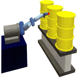
This figure shows a simulation of a
Robotics Research 7 DOF arm mounted to a Hermies-II mobile base
to give 10 DOF for the total system. The task being simulated is
inspecting 55 gallon drums for radiation leaks. The simulation
was developed in concert with ORNL. The redundancies in the
systems kinematics were resolved by optimizing a utility
function composed of 29 different performance criteria. ORNL was
investigating the feasibility of storing nuclear waste in big
farms and monitoring it automatically using robots until someone
could figure out how to react it some more to make it safe, or
just keep monitoring it for 1,000 years. This is a much better
idea than burying the waste. Of course it would be best not to
make it in the first place. The world would be better off
without nuclear weapons.
|
|
|
|
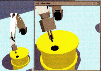
This figure shows a simulation of a Schilling Titan robot performing a gas-sampling task while monitoring 55 gallon drums. The simulation was developed in concert with INEL and showed the robot had enough accuracy inserting a 1/16" probe through a 1/8" vent.
The simulation took two days to develop, which at the time was
really fast. That might not seem so fast today. |
|
|
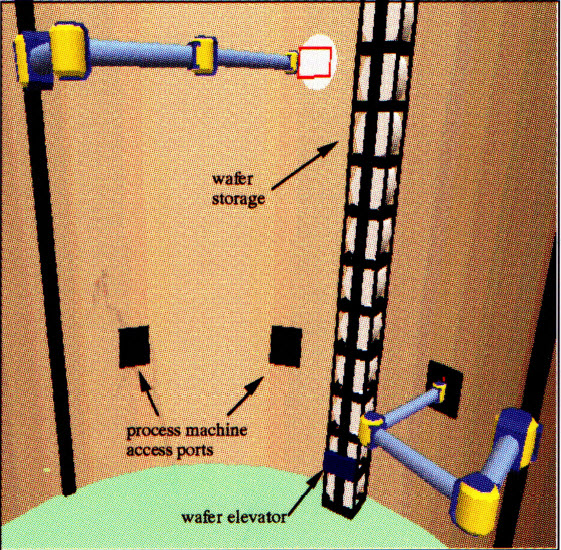
Advanced Semiconductor Manufacturing Facility - Center Core View
- No human intervention
- Each floor has 3 modular robots and 10 process machines
- Central elevators
- No single-point failures in critical path
|
|
|
|
|
This figure shows a
robot arm with a "crab claw" geometry. This geometry
is created by arranging three knuckle joints in series. It
is one of the hardest 6 DOF geometries for inverse
kinematics algorithms because its workspace is so limited and
the solution space is littered with singularities. This is a
classic test case for inverse
kinematics algorithms because of these challenges. It is known
the robot will be commanded to travel through singularities,
the question is how will the inverse algorithm respond? This
"three knuckle" serial geometry also formed for the
basis for a very high accuracy, tendon-driven surgical robot
with jeweled bearing at each degree of motion. |
|
|
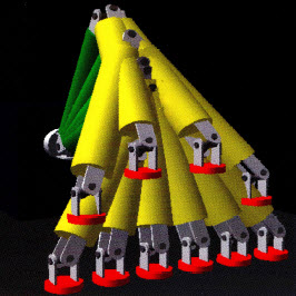
This figure shows frames from an
animation of the crab claw robot following a walking motion. The
inverse kinematics algorithm was able to solve for the placement
of the crab's "foot" in spite of the singularities and
joint range limitations of the underlying geometry. No inverse
algorithm can make a robot do something that is impossible, such
as move through a kinematic singularity, my solution was
singularity-free in the sense that it would never generate
impossible solutions, but would instead let the robot deviate
from the commanded path a small amount.
|
|
|
|
|
Rich Hooper, PhD, PE
Software, Robotics and
Computer Controlled Machines
|
|
|
|
|
|
|
© copyright Richard Hooper all rights reserved
|
|