|
ABSTRACT
Traditional methods of achieving manufacturing system safety exploit the highly repetitive nature of traditional manufacturing operations. With agile manufacturing systems, the interactions between machinery and personnel (operator, set-up, and maintenance) become less predictable. The smaller batches and more varied product drive hardware and software designs that are difficult to model and impossible (for all intents and purposes) to test exhaustively. Subsumptive fault-tolerance develops a multi-layered architecture where each successive layer incorporates the fault tolerance provided by all layers beneath. This approach assumes that faults will eventually occur in complex systems and attempts to trap these faults before they become safety concerns. Faults in manufacturing systems may include: unpredictable personnel behavior, software bugs, hardware flaws, and external events (such as power outages). The multi-layered subsumptive architecture should protect personnel even in the presence of multiple faults.
INTRODUCTION
This paper primarily discusses fault-tolerance at the machine level. In particular the paper focuses on machines that produce output motions, such as robots and computer controlled machine tools. The presentation divides into two main areas: hardware and software. The hardware section discusses two fault-tolerant actuators and a fault-tolerant actuator controller. The first actuator is a one Degree Of Freedom (DOF) device that is dual in the sense that there are two motors and gear reducers mounted on the same drive shaft. If either side fails,
the other can still drive the shaft to produce output motion. The second actuator is a two DOF device with four direct-drive motors. Two of the direct-drive motors drive each of the two output motions. With multiple redundant sensors, the actuator is implemented as a fault tolerance testbed. The final piece of hardware is a fault-tolerant electronic servo controller. This controller’s features include: multiple sensor interfacing, compact ‘smart’ power electronics, fault tolerance, and high speed digital communications designed in a modular package. The software section primarily discusses multi-criteria decision making. This decision making forms the basis of the fault tolerant control software. Essentially, the decision making software uses performance criteria to identify faults and determine a course of action in response.
HARDWARE
Dual Actuator
Existing drive systems usually include motor, encoder (or
resolver), brake, drive train and joint bearings. They have no fault tolerance capability and could suffer failure through a variety of modes. To provide fault tolerance, one option suggested at
NASA-JSC (Chladek, 1990) is to use multiple motors driving separate primary gears in a common gear box. This requires that all motors be capable of rotation at all times and any degradation in a motor's performance affects the joint. Another option uses dual motors driving a common axis through a bevel differential drive. This work suggests that such a drive system should have a high forward efficiency and low backdrive efficiency. Though this design can tolerate a failure of either motor, a failure in the differential will cripple the joint. Without complete functional duality, it is impossible to mask all the probable failure modes. It is, therefore, imperative that a dual actuator set driving a single joint be
designed.
 |
|
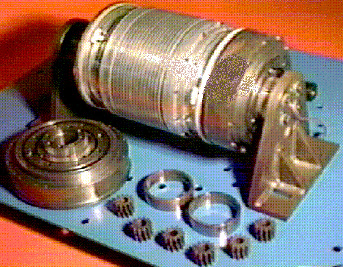
Figure 1. Dual Actuator on Test Stand |
Figure 1. shows a photograph of the actual module on
its test-stand. It is symmetrical about the center line and has
complete duality between the right and left halves. Each half
contains an armature, rare earth magnets, resolvers, brakes and
Ferguson's paradox epicyclic gear trains. The Ferguson's paradox
gear train was chosen primarily for its high gear ratio and
compactness. The module has attributes of low-weight,
high-stiffness, minimal interfaces to the system controller, and
overall compactness. The prototype of the module incorporates mainly
off-the-shelf components compactly laid out in a configuration that
provides low weight and high drive stiffness. The dual sided module
provides fault tolerance in the event of failure of one side by
"doubling up" on the other side by peaking its power for a
short period of time. In the event of seizure, the failed side has
to be detached from the power train to allow the joint to turn. For
the prototype actuator, such a detachment is necessary even in the
case when the failed motor is free to move because of the non-backdrivability
of Ferguson's paradox gear trains. Conceptually, a dual fault
tolerant actuator can be incorporated into fault tolerance at levels
II, III, and IV. The prototype module, however, is designed for
testing and development as a stand-alone unit and is mounted to a
heavy steel test stand
Knuckle
Fault-Tolerance Testbed
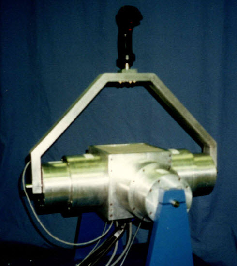
The knuckle is designed to tolerate a minimum of 1 fault before failing. The system controller acts as a supervisor in analyzing the sensory feedback with a Fault Detection and Isolation (FDI) algorithm to determine if a fault has occurred in the knuckle. If a fault occurs at the actuator level, the motor is removed by disengaging a clutch. Each servo system consists of a clutch, a brushless resolver, a brake, Hall-effect sensors, and a three-phase Brushless DC
motor.
 |
|
Figure 2. Knuckle Under Test |
An FDI algorithm supervises the servo systems. The topic of FDI enjoys a rich history in the literature. Roughly twenty years ago Willsky generated a survey paper presenting a number of statistical techniques for fault detection in dynamic systems. Over ten years ago Isermann developed another survey paper on fault detection based on modeling and estimation methods. NASA also has shown considerable work in the area of FDI, including applications to a multi-sensor navigation system and to the space shuttle’s main engines. As one would hope, FDI is also important within the nuclear power industry. Singer et al. discuss the use of sequential statistical techniques in the analysis of the primary coolant pumping system in the EBR-II nuclear reactor. An expert system using pattern recognition and fuzzy inference techniques analyzes the statistical information to provide the fault detection. More recent work includes that of Visinski on fault detection thresholds based on dynamic system models. By including multiple redundant sensors in each servo system, as well as complete redundant servo systems, the knuckle was designed specifically for implementing and testing these types of algorithms.
In the current algorithm for the knuckle testbed, the servo control systems are assumed to be fully observable, deterministic, and linear time invariant. When an observable, accurate model exists, the FDI implementation uses parameter identification methods for detecting and, in many cases, isolating faults. The FDI algorithm also makes use of the currents in the DC servo system to determine whether enough torque can be generated to provide the motion desired. Threshold levels are set to check for deviations outside of the nominal values (which are determined experimentally) and any such deviations are classified as faults. The algorithm also filters “false alarms” generated by transient responses or noise levels outside the allotted error bands.
Digital
Integrated Servo Controller (DISC)
The DISC is a very compact brushless DC servo controller that offers numerous features not contained in any single commercial system available today. c The features incorporated into each DISC allows for research into the use of distributed control applied to fault-tolerant systems. Distributed control can significantly reduce the amount of wires running through a structure since the DISCs digitally multiplex the signals locally. This reduction in wires is essential to the success of mechanical fault tolerance. The DISC contains four sub-modules: a sensor interface module, a communications module, a power interface module and a digital
controller.
One of the DISC’s advanced capabilities is its inherent fault tolerance. Two DISCs connect in tandem with two motors to actuate a single degree of freedom. In the event of a motor or sensor failure, a DISC can alert the system controller, and either shut itself down and allow operation to continue with only one motor, or try to isolate the fault and continue operation. Since a DISC uses parallel communication to talk to another DISC and it has control of the opposing Power Enable signal, two parallel DISCs act as a watchdog to each other. Thus, if a DISC were to fail, then the other DISC could detect the fault, alert the system controller, disable the faulty controller, disengage the clutch on the faulty controller, and continue operation with only one motor.
 |
|
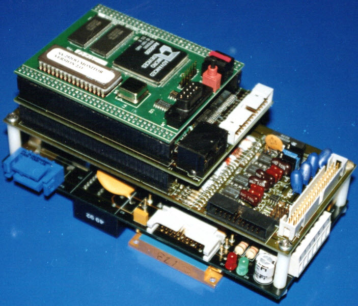
Figure 3. Digital Integrated Servo
Controller (DISC) |
Power Interface Module: The power interface controls the power to the actuator. It includes the power electronics and drivers, the clutch and brake control, and the current sensors. The DISC derives the motor commutation in software. In order to simplify the interface between the digital controller and the power interface, the power module uses a smart power electronic device. Smart power devices contain analog and/or digital circuitry in addition to the discrete power electronics. The device chosen for the DISCs generates the bias voltages for the high side discrete transistors as well as performing the lockout function for the input PWM logic.
Sensor Interface Module: The sensor module conditions and digitizes all external signals before passing them to the controller module. The module will read multiple sensors, including: a tachometer (16 bit resolution), three current sensors (12 bit resolution), a resolver (16 bit resolution), a torque sensor (12 bit resolution), an incremental encoder (16 bit resolution), two temperature sensors (8 bit resolution), a logic level Hall-effect sensor, an auxiliary +/- 5V signal (8 bit resolution) and an auxiliary +/- 10V signal (8 bit resolution). Each of the 12 and 16 bit analog signal lines has an anti-aliasing filter with a digitally adjustable cut-off frequency. As a precaution, the sensor module monitors the total actuator current with analog circuitry and if an over-current occurs, the analog circuitry shuts the system down.
The sensor interface module uses a five channel timing controller. Three channels function as a scheduler for sampling of the signals. The other two channels adjust the clock frequency of the anti-aliasing filters. The timer is software programmable.
Closed-Loop Controller Module: The closed-loop controller was purchased as an off-the-shelf component. The module is an Advanced Micro Device’s SA-29200™ Demonstration Board. This card utilizes the Am29200 RISC microcontroller. The board has the following features: 512 KBytes of ROM, one MByte of DRAM, an RS-232 serial port, a JTAG port, two expansion connectors allowing full access to all processor signals, and a resident debugger. The system operates from a 5V power supply. The Am29200 is a 16 MHz, 32 bit integer processor with a ROM controller, a DRAM controller, an interrupt controller, a PIA controller, a 16 bit I/O port, a serial port, and a parallel port.
Communications Module: The communications module controls the information between the DISCs and the system controller. This module fulfills a fundamental function in the distributed control techniques demanded by fault-tolerant machines. In distributed control each actuator has its own local intelligent controller that is mounted either adjacent to or directly inside the actuator. The local controller performs all necessary sensor processing and power conversion required for movement of the particular joint. The basic components of a local controller would include a central processing unit, a sensor interface, a power interface, and a communications interface.
The only external connections this local controller requires are for power and information. Since the local controller incorporates the power electronics interface, the power connections can be made to a common power bus that is used by all actuators in the system. Similarly, the information connections link the local controller to a simplified system controller through a serial digital communications bus. This communications bus carries all the information required to command each joint (where it should move and at what velocity torque). Depending on the types of power and communication buses the total number of wires can be less than ten. This potential drastic reduction in the number of wires required to run throughout a fault-tolerant system makes distributed control the method of choice.
>
|